
Understanding Manual Transfer Switches
Manual transfer switches offer a cost-effective backup power solution, requiring hands-on operation to switch between utility and generator power sources.
These devices are crucial for safely connecting portable generators, preventing dangerous backfeeding into the power grid during outages.
Understanding their function is key to reliable emergency power, especially with increasingly severe weather events impacting power availability.
What is a Manual Transfer Switch?
A manual transfer switch is a vital electrical device installed alongside your main service panel, acting as a safe intermediary between your home’s electrical system and a portable generator.
Unlike automatic transfer switches, it requires manual operation – you physically switch the power source when an outage occurs. This switch overrides the utility power, allowing generator power to flow to selected circuits.
Crucially, it prevents backfeeding – electricity flowing back into the power grid – which is extremely dangerous to utility workers and can damage equipment. It’s a cost-effective solution for backup power, offering flexibility and control.
Why Choose a Manual Transfer Switch?
Manual transfer switches present a compelling option for homeowners seeking affordable and reliable backup power. They are significantly less expensive than automatic systems, offering a cost-effective solution for occasional outages.
Their simplicity allows for greater control; you decide when to switch to generator power. They’re ideal for those comfortable with a hands-on approach and utilizing portable generators.
Furthermore, they offer flexibility, allowing you to power specific essential circuits, conserving generator fuel and extending runtime during prolonged power disruptions.
Preparation for Installation
Careful preparation is vital before installing a manual transfer switch, including gathering necessary tools and materials and prioritizing safety precautions.
Proper planning ensures a smooth and secure installation process, safeguarding against electrical hazards.
Tools and Materials Needed
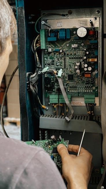
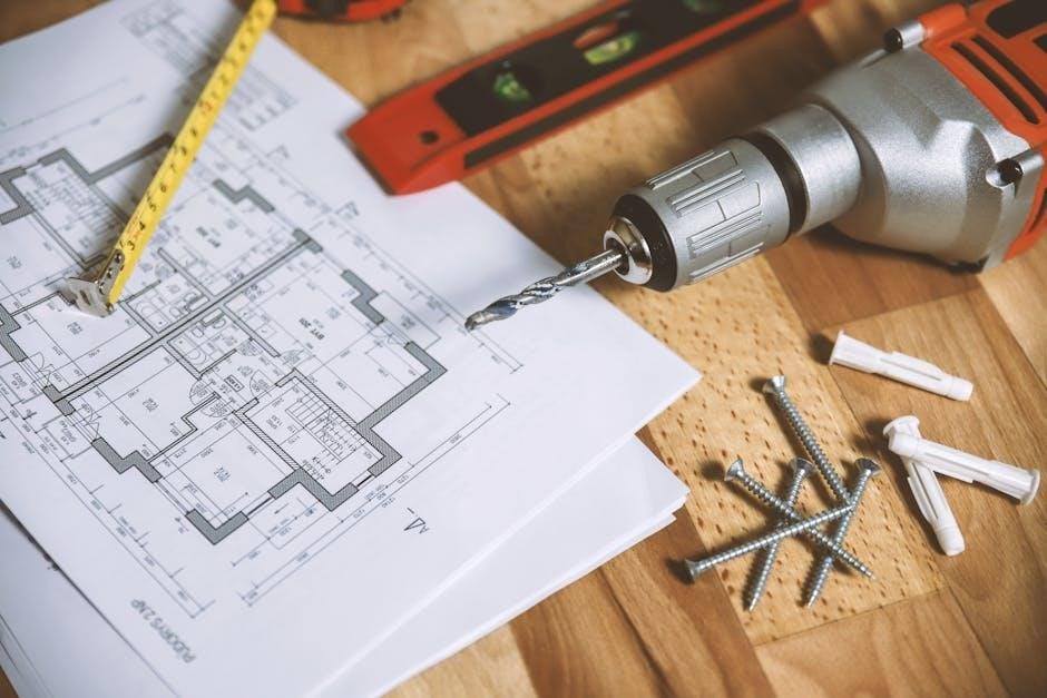
Essential tools include screwdrivers (various types), wire strippers, pliers, a voltage tester, and a circuit tester for safe verification. Materials encompass the manual transfer switch itself, appropriately sized wiring (matching existing service), wire connectors, conduit for wiring protection, and mounting hardware.
You’ll also require electrical tape, labels for clear circuit identification, and potentially a new circuit breaker depending on the switch’s requirements. A flashlight and safety glasses are crucial for visibility and protection during installation. Always confirm local code requirements for specific material specifications.
Safety Precautions
Always disconnect the main breaker before commencing any electrical work to eliminate shock hazards. Verify the power is off using a voltage tester. Never work alone; have someone nearby in case of emergencies. Wear appropriate personal protective equipment, including safety glasses and insulated gloves.
Understand local electrical codes and obtain necessary permits. Avoid working in wet conditions. Double-check all wiring connections before restoring power. If unsure about any step, consult a qualified electrician – safety is paramount!
Mounting the Transfer Switch
Securely mount the transfer switch near the main service panel, ensuring accessibility and adherence to local codes for proper operation and maintenance.
Location Considerations
Choosing the right location for your manual transfer switch is paramount for both safety and functionality. Proximity to the main electrical service panel minimizes wiring runs and voltage drop.
Ensure the chosen spot is easily accessible, allowing for convenient operation during power outages, but also protected from the elements and potential physical damage.
Consider a dry, well-lit area with sufficient space around the switch for comfortable and safe working conditions during installation and future maintenance. Adhering to local electrical codes regarding clearances is essential.
Physical Mounting Process
Securely mounting the transfer switch is critical for safety and reliable operation. Begin by marking and drilling pilot holes into the wall, ensuring they align with the mounting holes on the switch enclosure.
Use appropriate wall anchors or screws suitable for the wall material – wood, drywall, or concrete – to provide a robust and stable attachment.
Verify the switch is level before fully tightening the screws. A properly mounted switch minimizes vibration and ensures all internal connections remain secure during operation.
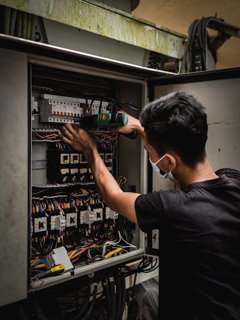
Connecting to the Main Service Panel
Connecting to the main panel involves carefully identifying circuit breakers and wiring both the line and load sides of the transfer switch.
This step demands strict adherence to electrical codes and safety protocols to prevent hazards and ensure proper functionality.
Identifying Circuit Breakers
Before commencing any wiring, meticulously identify the circuit breakers within your main service panel. This crucial step involves labeling each breaker to correspond with the circuits they control throughout your home.
Determine which circuits you intend to power with the generator during an outage – prioritize essential loads like refrigerators, heating systems, and lighting.
Carefully note the amperage rating of each selected breaker, as this information is vital for selecting the appropriately sized wiring and ensuring the transfer switch’s capacity aligns with your needs. Accurate identification prevents overloading and ensures safe operation.
Wiring the Line Side
The line side of the manual transfer switch connects directly to the main service panel, receiving power from the utility grid. This requires carefully disconnecting the appropriate circuit breakers identified earlier.
Using appropriately sized wiring, connect the line side terminals of the transfer switch to the corresponding breaker connections in the main panel.
Ensure all connections are secure and follow local electrical codes. Proper grounding is paramount for safety; connect the ground wire to the designated grounding terminal within the service panel and the transfer switch.
Wiring the Load Side
The load side of the manual transfer switch distributes power to selected circuits within your home during a generator-powered event. Identify the circuits you wish to power – essential appliances and lighting are common choices.
Disconnect the breakers for these circuits in the main panel. Then, connect the load side terminals of the transfer switch to the corresponding wires leading to those circuits.
Double-check all connections for tightness and correct polarity, adhering strictly to electrical code requirements for a safe and functional setup.
Generator Connection
Connecting the generator involves matching its specifications to the transfer switch’s inlet, ensuring compatibility. Proper wiring prevents backfeeding and ensures safe power transfer.
Utilize appropriately sized cables and connectors for a secure and reliable connection during emergency power needs.
Generator Specifications and Compatibility
Ensuring generator compatibility is paramount for safe and effective operation with a manual transfer switch. Carefully review the generator’s voltage, amperage, and wattage ratings. These must align with the transfer switch’s specifications to prevent overload or damage.
Portable generators are typically used with manual transfer switches, unlike permanently installed standby generators. Confirm the transfer switch is rated for the generator’s output. Incorrect matching can lead to equipment failure or pose a significant safety hazard, potentially causing fires or electrical shock.
Always prioritize safety and consult a qualified electrician if unsure about compatibility.
Wiring the Generator Inlet
The generator inlet, located on the transfer switch, requires careful wiring to establish a secure connection. Typically, a heavy-duty power cord from the generator plugs into this inlet. Ensure the cord is appropriately sized for the generator’s output and the distance to the switch.
Proper grounding is critical; the generator and transfer switch must be correctly grounded to prevent electrical shock. Follow the manufacturer’s instructions meticulously, paying close attention to wire gauge and connection tightness. Incorrect wiring can create a dangerous situation.
Double-check all connections before operation.
Single-Phase Wiring Diagrams
Single-phase configurations are common for residential setups, utilizing a straightforward wiring scheme for connecting the generator to essential circuits via the switch.
Diagrams illustrate line, load, and neutral connections, ensuring safe and efficient power transfer during outages.
Typical Single-Phase Configuration
A typical single-phase setup involves a manual transfer switch positioned near the main electrical panel. The “line side” connects to the panel’s circuit breaker, receiving utility power normally.
The “load side” wires connect to selected circuits you want powered by the generator – often essentials like refrigerators, lights, and heating systems.
Neutral and ground wires are crucial for safety; diagrams clearly show their proper connections.
This configuration allows manual switching between utility and generator power, isolating the generator from the grid to prevent backfeeding.
Detailed Wiring Steps ー Single Phase
First, disconnect main power at the breaker. Connect the line side wires from the panel to the transfer switch’s corresponding terminals. Next, wire the load side, carefully selecting circuits for backup power and connecting them to the switch.
Ensure proper grounding and neutral connections, following the diagram precisely;
Double-check all connections for tightness and accuracy before proceeding.
Finally, connect the generator inlet, ready for power transfer when utility service is interrupted, always prioritizing safety and code compliance.

Three-Phase Wiring Diagrams
Three-phase transfer switches require meticulous wiring, connecting each phase and neutral to both the main panel and generator inlet for balanced power distribution.
Proper sequencing is vital.
Typical Three-Phase Configuration
A typical three-phase manual transfer switch configuration involves a double-throw design, allowing selection between utility power and generator supply. Each phase (L1, L2, L3) is independently connected to both sources.
Neutral wiring is also crucial, often shared between sources, but specific configurations vary. The switch incorporates appropriately sized circuit breakers for each phase, protecting against overloads.
Grounding is paramount for safety, ensuring a solid connection to earth. Detailed diagrams illustrate the precise wiring sequence, emphasizing correct phase matching for optimal performance and preventing damage.
Detailed Wiring Steps ⎼ Three Phase
Begin by disconnecting main power and identifying the three-phase lines (L1, L2, L3) at the service panel. Connect these to the line side of the transfer switch. Next, run appropriate gauge wiring from the generator inlet to the generator side of the switch.
Carefully match phases during connection, ensuring correct L1-L1, L2-L2, and L3-L3 alignment. Securely tighten all connections and verify proper grounding.
Double-check wiring against a verified diagram before energizing, prioritizing safety and accurate phase sequencing.

Testing the Transfer Switch
Initial testing involves safely powering the generator and switching to it, verifying power to connected loads. Load testing confirms the switch handles expected power demands.
Proper function ensures seamless transitions during outages, safeguarding appliances and critical systems.
Initial Power-Up Test
Before starting the generator, ensure the transfer switch is in the “utility” position. Then, safely start the generator following the manufacturer’s instructions. Slowly switch the transfer switch to the “generator” position, observing for any unusual sounds or smells.
Verify power is now supplied to the circuits connected to the load side of the switch. Use a multimeter or test lights to confirm voltage presence. Carefully check that only intended circuits are energized, avoiding accidental power to unused lines.
This initial test confirms basic functionality and safe operation before applying a significant load.
Load Testing Procedure
After the initial power-up, gradually apply loads to the circuits connected through the transfer switch. Start with smaller appliances and progressively add larger ones, monitoring the generator’s performance. Observe for any voltage drops or signs of overload, such as the generator struggling to maintain speed.
Ensure the total load does not exceed the generator’s rated capacity. Regularly check the transfer switch for overheating or unusual noises during load testing. This validates the system’s ability to handle real-world power demands safely.
Document the maximum load sustained without issues.
Important Considerations
Code compliance and permits are essential for safe installation. Manual transfer switches have limitations; they require manual operation and are for portable generators only.
Code Compliance and Permits
Ensuring adherence to local electrical codes is paramount when installing a manual transfer switch. Many jurisdictions require permits for electrical work, including generator connections, to guarantee safety and proper installation.
Failing to obtain necessary permits can result in fines and necessitate rework. Consult your local building department to understand specific requirements regarding wiring, grounding, and switch placement.
Properly documented inspections verify the installation meets safety standards, protecting your home and family. Always prioritize safety and legal compliance throughout the entire process.
Limitations of Manual Transfer Switches
Manual transfer switches necessitate a hands-on approach; power isn’t automatically restored during outages. They are designed for use with portable generators, unlike automatic systems compatible with standby generators.
You must physically switch to generator power, and carefully manage generator fuel levels. These switches don’t offer the seamless transition of automatic units, and only power selected circuits.
Consider your needs – if uninterrupted power is critical, an automatic transfer switch might be a better investment despite the higher cost and complexity of installation.
Maintenance and Troubleshooting
Regularly inspect the transfer switch for loose connections and signs of corrosion, especially at wiring terminals. Test the switch’s operation periodically by simulating a power outage and switching to generator power.
If the switch fails to operate smoothly, or if you notice any unusual noises or smells, immediately disconnect the generator and consult a qualified electrician.
Ensure proper generator maintenance – fuel stability and oil levels – as generator issues can mimic transfer switch problems. A well-maintained system ensures reliable backup power.
Portable Generator Compatibility
Manual transfer switches are specifically designed for use with portable generators, offering a safe and flexible backup power solution for homes.
Proper wattage matching and avoiding backfeeding are critical considerations when connecting a portable generator to a transfer switch.
Specific Generator Requirements
Ensuring generator compatibility is paramount for safe operation with a manual transfer switch. Carefully assess the generator’s wattage output, verifying it meets or exceeds the combined wattage of the circuits you intend to power during an outage.
Consider the generator’s voltage and phase (single or three-phase) to match the transfer switch’s specifications. Proper grounding is essential, and the generator must adhere to local electrical codes.
Using the correct inlet connector and cable size is also crucial for a secure and efficient connection, preventing overheating and potential hazards.
Avoiding Backfeeding Issues
Backfeeding – sending power back onto the utility grid – is extremely dangerous and illegal. A manual transfer switch is specifically designed to prevent this by physically isolating your home’s electrical system from the utility lines when the generator is running.
Correct wiring is absolutely critical. The switch must completely disconnect the main service panel from the grid before connecting the generator.
Never attempt to bypass the transfer switch or directly connect a generator to a wall outlet, as this creates a severe electrocution and fire hazard for utility workers and neighbors.
Automatic vs. Manual Transfer Switches
Automatic transfer switches operate seamlessly, while manual switches require user intervention. Manual options are more affordable and suitable for infrequent power outages.
Wiring diagrams differ significantly; automatic systems are more complex, needing professional installation for safe and reliable operation.
Key Differences Explained
Manual transfer switches demand physical engagement to switch power sources, unlike automatic systems that do so autonomously. Wiring a manual switch involves connecting the generator inlet to designated circuits, requiring careful adherence to a wiring diagram.
Automatic switches integrate sophisticated sensors and controls, automatically detecting outages and initiating the transfer. They are generally more expensive and necessitate professional installation. Manual switches offer a budget-friendly alternative, ideal for occasional use, but require user awareness and action during power failures.
The diagram for a manual switch illustrates the specific connections needed for safe operation, emphasizing the importance of isolating the main power supply.
When to Choose Manual Over Automatic
Opt for a manual transfer switch if cost is a primary concern and you’re comfortable with a hands-on approach to restoring power. A clear wiring diagram is essential for safe and correct installation, typically involving a portable generator.
If outages are infrequent and you don’t require seamless power restoration, a manual switch is a practical choice. Automatic systems excel in critical applications demanding uninterrupted power, but come with a higher price tag and installation complexity.
Understanding the diagram ensures you can safely connect and disconnect your generator as needed.
Advanced Wiring Scenarios
Manual transfer switch wiring diagrams can be customized for specific appliances or expanded capacity, requiring careful planning and adherence to electrical codes.
Wiring for Specific Appliances
Wiring for specific appliances with a manual transfer switch demands careful circuit load calculations. Prioritize essential devices like refrigerators, furnaces, and medical equipment. Dedicated circuits are recommended for high-demand appliances to prevent overloading the generator.
Consult appliance manuals for wattage requirements and factor in starting wattage, which is often higher than running wattage. Properly sized wiring and breakers are crucial for safety and optimal performance. Detailed manual transfer switch wiring diagrams should reflect these specific appliance needs, ensuring a reliable backup power solution tailored to your household.
Expanding Transfer Switch Capacity
Expanding transfer switch capacity often involves adding a subpanel connected to the transfer switch’s load side. This allows for powering more circuits than the switch initially supports. Careful planning and adherence to electrical codes are paramount when undertaking this modification.
Detailed manual transfer switch wiring diagrams are essential for safely integrating the subpanel. Ensure the generator’s capacity can handle the increased load. Professional assistance is highly recommended to avoid overloading circuits and maintain a secure, reliable backup power system.